Pressure reversing valves
Pressure controlled reversing hydraulic valves
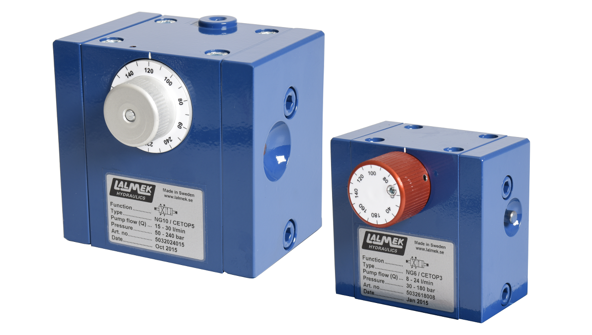
Lalmek Hydraulics’ unique and proven pressure reversing directional control valves automatically create a forward and return movement without electrical components and thus replaces end-position switches and pressure switches.
The valves feature an integrated pressure relief function that protects the hydraulic system against overpressure. The function of the valve is gradual reversing, which prevents pressure peaks while sparing other components in the hydraulic system.
In applications with long hydraulic connections and where pressure drops occur, the valve compensates for the pressure drop by shunting a part of the oil flow to the oil reservoir. This means that the required working pressure is reached in the whole system before the valve switches the direction of the oil.
The directional valve is equipped with a setting dial where the reversing pressure and pressure relief are set at the same time, which means tools and a pressure gauge are not needed. It is also equipped with a manual function to switch the oil direction when necessary.
The valve is available in both NG6 and NG10 designs.
Common application areas include pressurised manure handling, solid fuel plants and waste compactors.
As an extra accessory there is an option that always starts the valve with a return movement, e.g. in a waste compactors.
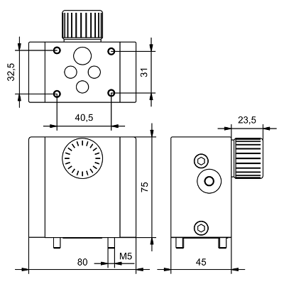
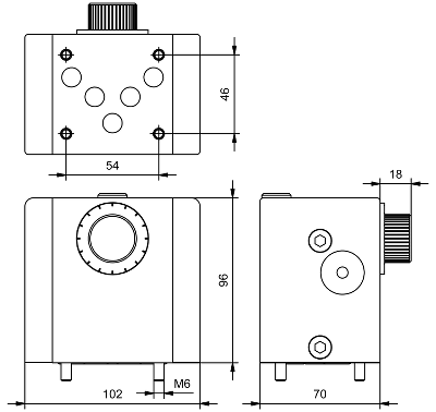
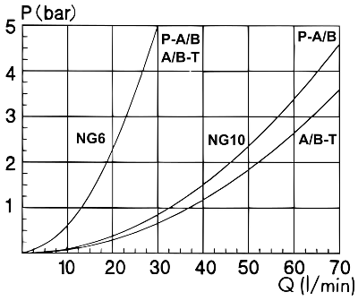
Dimensional drawing and pressure drop curve
Pressure reversing hydraulic valve NG6.
Pressure reversing hydraulic valve NG10.
Pressure drop curve.
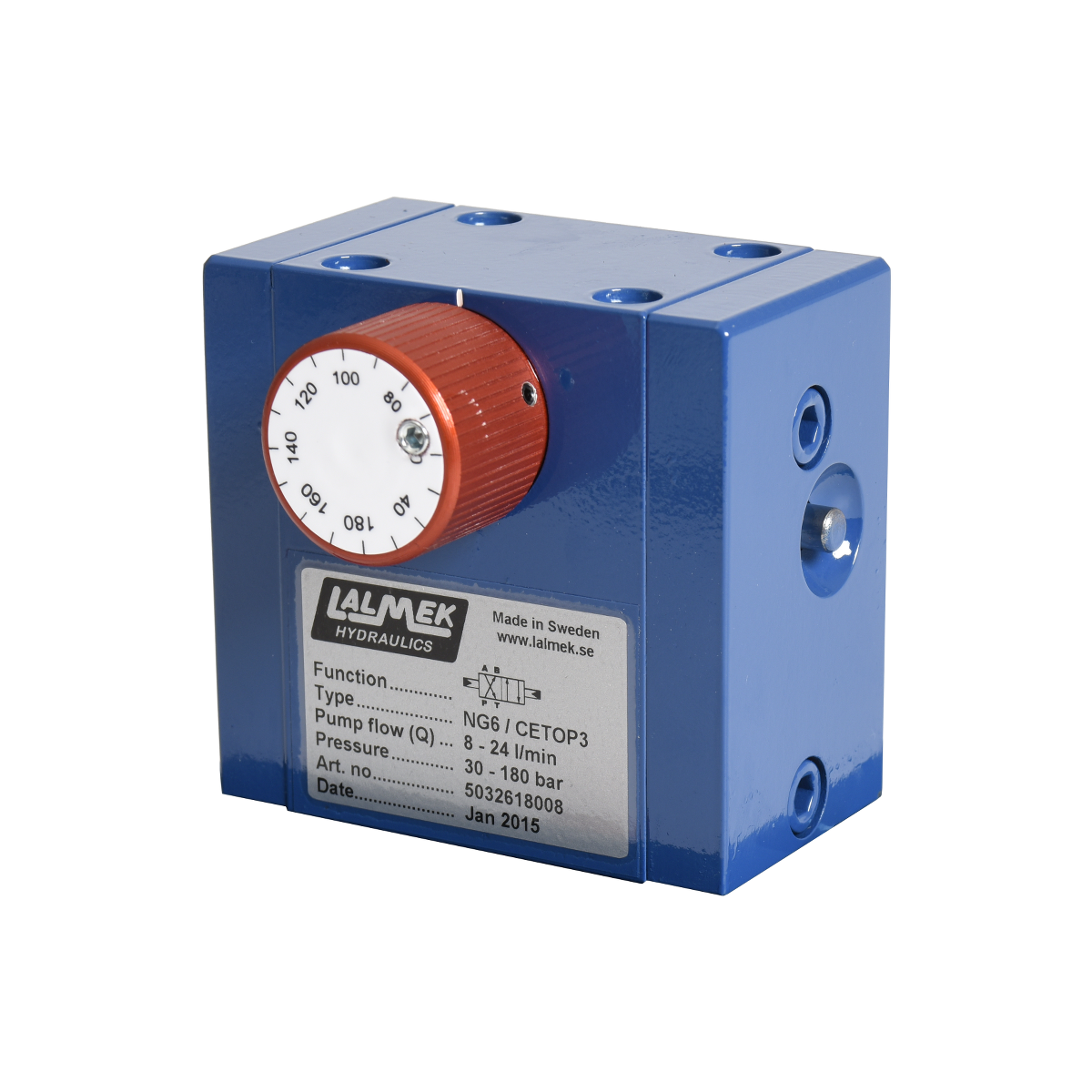
Pressure reversing hydraulic valve NG6
Pressure reversing directional control valve NG6.
| Description | Data |
|---|---|
| Hole pattern: | NG6, CETOP 03, ISO 4401, DIN 24340 |
| Valve: | 4/2 pressure reversing |
| Flow (Q): | For optimal performance each valve is adapted for a specific pump flow range between 0.5-30 l/min |
| Pressure range: | 40-250 bar (4-25 MPA) |
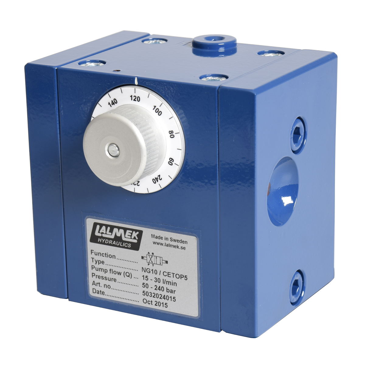
Pressure reversing hydraulic valve NG10
Pressure reversing directional control valve NG10
| Description | Data |
|---|---|
| Hole pattern: | NG10, CETOP 05, ISO 4401, DIN 24340 |
| Valve: | 4/2 pressure reversing |
| Flow (Q): | For optimal performance each valve is adapted for a specific pump flow range between 5-60 l/min |
| Pressure range: | 40-250 bar (4-25 MPA) |