Hydraulic cylinders - PARALLEX
Hydraulic cylinders - PARALLEX
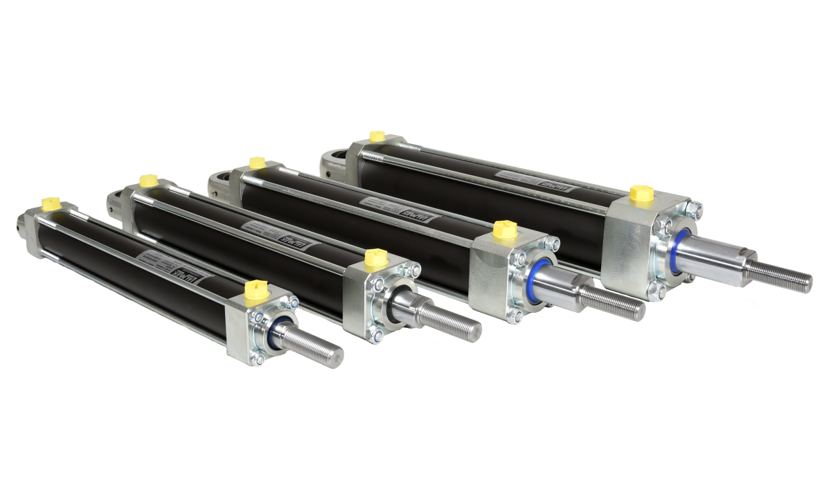
Using Lalmek PARALLEX we can get up to six tie rod hydraulic cylinders to work in a synchronised movement and always keep the right level and the right carrying capacity irrespective of how the load is distributed on each cylinder.
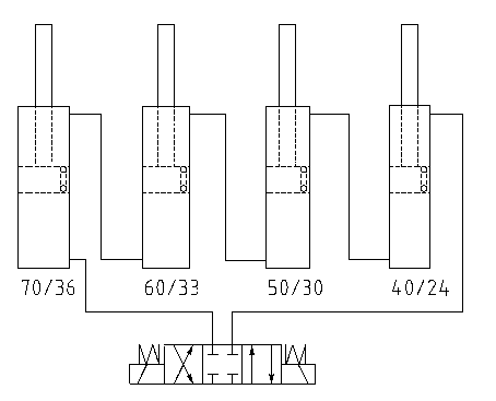
The system is based on the volume ratio between a number of hydraulic cylinders that are connected in series, which means that they always move in sync. The hydraulic cylinders are equipped with a function that means they are calibrated each time they reach an end position. Parallelism is therefore almost exact as the right quantity of oil is always maintained between the cylinders. This function can also be used when bleeding the system.
The hydraulic cylinders are of the tie-rod type where the cylinder is screwed together with four tie-rods. This design is ideal for demanding applications where vibration and pressure peaks are common as there are no welded joints.
The cylinders can be supplied with a number of different fastening options at both the piston rod end and the cylinder short end, such as spherical ends, internal or external threads or for mounting with bolted joints.
Lalmek PARALLEX can be equipped with integrated linear sensors that state the position of the piston rod with great accuracy.
Examples of suitable applications for Lalmek PARALLEX include lifting systems for materials handling and vehicle assembly, height adjustable work stations within industry, hydraulic presses and other production equipment where demands on synchronised movements are high.
The image shows a hydraulic schematic for series connected hydraulic cylinders with compensation functionality.
Installation, operation and troubleshooting
Use thick walled hydraulic pipe with so small internal diameter as possible and where the pressure drop in the pipes is taken into consideration. If it is not possible to use hydraulic pipe throughout, double reinforced hydraulic hose can be used on sections where required, however, parallelism will be impaired.
These measures reduce the deviation between the cylinders due to the elasticity in the oil, the pipes and the cylinder tube. If, for example, a table is to be lifted, place the cylinders as far out in the corners as possible to avoid the transmission of small misalignment that despite everything may occur.
Exercise extreme care so that no contamination enters the system.
Blow clean (and if necessary wash) and check each pipe after cutting. Check each adapter before use. Do not remove the plugs from the hydraulic cylinders until the pipe is to be fitted.
Installation
• Cut the hydraulic pipes to the right length.
• Blow the pipes clean and check that they are absolutely clean.
• Fit the hydraulic pipe/hose from the hydraulic power pack to the rear short-end of the largest cylinder.
• Continue from the piston rod side of the largest cylinder to the rear short-end on the next largest, etc.
• On single acting systems a pipe must be connected from the piston rod side on the smallest cylinder to the tank.
Bleeding PARALLEX cylinders
Note that the cylinders should be run unassembled during start up. They will not run in parallel if there is air in the system.
• Turn the cylinder so that the piston rod is positioned upwards or downwards, not horizontal (single acting systems upwards).
• Run the cylinders to the end positions and allow the pump to run for approx. 60 to 120 seconds with 30 - 50 bar pressure.
• Run to the other end position and allow it to pump for 60 seconds even here (single acting systems sink to the bottom).
• Repeat a few times.
• During final bleeding increase the pressure to maximum pressure or max. 200 bar.
Bleeding for vertical assembly, cylinders with piston rod upwards
The cylinders are bled by forcing the oil in on the positive side of the largest cylinder. When the piston rod on cylinder 1 has reached its upper end position a bypass passage* opens to cylinder 2.
Continue in the same way with cylinders 3 and 4 if installed in the system. When the last cylinder has reached its upper end position the oil pressure must remain for a further 3 - 5 minutes so that the trapped in air has time to flow out from the last cylinder’s pipe and back to the oil tank.
Bleeding can take 10 - 50 minutes as the bypass passage can only let through approx. 0.5 l oil a minute.
It is suitable to adjust the pressure on the pressure limiter down to 50 bar when bleeding to ensure the oil does not become warm.
Bleeding for vertical assembly, cylinders with the piston rod downwards
Cylinders that have the piston rod turned downwards are bled in the reverse order.
The oil pressure is run in on the smallest cylinder’s negative side until air-free oil flows out from the largest cylinder’s positive side.
Bleeding with cylinders mounted horizontally
Cylinders that are mounted horizontally are bled through the bypass passage* in the cylinder tube. In order for bleeding to work it is important that the bypass passage in the cylinder tube is turned upwards. The bypass passage is marked on the cylinder tube with red paint. As standard it is turned to the same side as the thread connections. State when ordering how the connections are to be placed. It is also possible to adjust the cylinder so that the bypass passage faces upwards by loosening the cylinder’s tie-rods and then turning the cylinder tube.
IMPORTANT!
In order to maintain the system’s parallel movement pattern and to compensate for internal micro-leakage the cylinders must have reached their end positions at least once every 20 – 100 strokes.
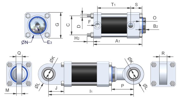
| Max. pressure (bar) | (Max. pressure on request) | Pressure force at 200 bar (tonne) | Tractive force at 200 bar (tonne) | Pressure area (cm²) | Tractive area (cm²) | Cylinder diameter (int.) | Piston rod diameter | A ± 2mm | B (2) | C | D | E (3) | F | G | H (2) | I ± 2mm (1) | J | K | L | M (bearing housing width) | N (tolerance f8) | O | P | Q (ball width) | R (bearing housing width) | S | T (1) | |
|---|---|---|---|---|---|---|---|---|---|---|---|---|---|---|---|---|---|---|---|---|---|---|---|---|---|---|---|---|
| 25/16 | 300 | 1 | 0,6 | 4,9 | 2,9 | 25 | 16 | 90 | 10 | 28 | M6 | M10 | G1/4" | 40 | >15 | 138,5 | 20 | 12 | 40 | 12 | 27 | 8 | 27,5 | 10 | 12 | 27,5 | 51 | |
| 32/20 | 260 | 300 | 1,6 | 1 | 8 | 4,9 | 32 | 20 | 96 | 10 | 32,6 | M6 | M10 | G1/4" | 45 | >15 | 146,5 | 18 | 15 | 47 | 18 | 34 | 10 | 32,5 | 12 | 18 | 26,5 | 58 |
| 40/24 | 290 | 300 | 2,5 | 1,6 | 12,6 | 8 | 40 | 24 | 105 | 10 | 41 | M8 | M12 | G1/4" | 55 | >20 | 167,5 | 27,5 | 20 | 55 | 20 | 42 | 10 | 35 | 16 | 20 | 25,5 | 69 |
| 40/30 | 290 | 300 | 2,5 | 1,1 | 12,6 | 5,5 | 40 | 30 | 105 | 10 | 41 | M8 | M12 | G1/4" | 55 | >20 | 167,5 | 27,5 | 20 | 55 | 20 | 42 | 8 | 35 | 16 | 20 | 25,5 | 69 |
| 50/30 | 200 | 260 | 3,9 | 2,5 | 19,6 | 12,6 | 50 | 30 | 123 | 10 | 48 | M8 | M12 | G3/8" | 62 | >20 | 190 | 31 | 25 | 62 | 25 | 52 | 10 | 40 | 20 | 25 | 37 | 74 |
| 60/33 | 200 | 280 | 5,7 | 3,9 | 28,3 | 19,6 | 60 | 33,2 | 131 | 10 | 58 | M10 | M16 | G3/8" | 80 | >25 | 207 | 35 | 30 | 80 | 30 | 62 | 10 | 45 | 22 | 30 | 42 | 77 |
| 60/40 | 200 | 280 | 5,7 | 3,1 | 28,3 | 15,7 | 60 | 40 | 131 | 10 | 58 | M10 | M16 | G3/8" | 80 | >25 | 207 | 35 | 30 | 80 | 30 | 62 | 10 | 45 | 22 | 30 | 42 | 77 |
| 70/36 | 230 | 280 | 7,7 | 5,7 | 38,5 | 28,3 | 70 | 36 | 131 | 10 | 66 | M12 | M20 | G1/2" | 88 | >25 | 263 | 61 | 35 | 83 | 21 | 70 | 10 | 71 | 25 | 30 | 33 | 82,5 |
| 80/39 | 200 | 240 | 10,1 | 7,7 | 50,3 | 38,5 | 80 | 38,7 | 134,3 | 10 | 74 | M12 | M20 | G1/2" | 100 | >25 | 266,3 | 61 | 35 | 83 | 21 | 80 | 10 | 71 | 25 | 30 | 34 | 85,3 |
| 80/60 | 200 | 240 | 10,1 | 4,4 | 50,3 | 22 | 80 | 60 | 144,3 | 20 | 74 | M12 | M20 | G1/2" | 100 | >25 | 286,3 | 61 | 35 | 83 | 21 | 80 | 10 | 81 | 25 | 30 | 44 | 85,3 |
| 100/60 | 200 | 15,7 | 10,1 | 78,5 | 50,3 | 100 | 60 | 178 | 20 | 90 | M16 | M24 | G1/2" | 120 | >30 | 374 | 88 | 50 | 123 | 30 | 92 | 15 | 108 | 35 | 40 | 60 | 101 | |
| 100/75 | 200 | 15,7 | 6,9 | 78,5 | 34,3 | 100 | 75 | 178 | 20 | 90 | M16 | M24 | G1/2" | 120 | >30 | 374 | 88 | 50 | 123 | 30 | 96 | 15 | 108 | 35 | 40 | 60 | 101 | |
| 125/75 | 210 | 240 | 24,5 | 15,7 | 122,7 | 78,5 | 125 | 75 | 178 | 20 | 114 | M20 | M24 | G1/2" | 150 | >40 | 374 | 88 | 50 | 123 | 30 | 105 | 15 | 108 | 35 | 40 | 60 | 101 |
| 160/100 | 250 | 40,2 | 24,5 | 201,1 | 122,5 | 160 | 100 | 210 | 20 | 150 | M30 | M42 | G3/4" | 200 | >50 | 492 | 141 | 80 | 180 | 47 | 150 | 15 | 161 | 55 | 60 | 54,3 | 115,8 | |
| 200/120 | 290 | 290 | 62,8 | 40,2 | 314,2 | 201,1 | 200 | 120 | 293 | 20 | 190 | M36 | M80x3 | G1 1/4" | 250 | >50 | 170 | 100 | 250 | 163 | 20 | 70 | 70 | 77 | 188,5 | |||
| 250/150 | 300 | 98,2 | 62,8 | 490,9 | 314,2 | 250 | 150 | 265,5 | 40 | 244 | M45 | M100x3 | G1 1/4" | 320 | >75 | 210 | 120 | 360 | 200 | 20 | 85 | 90 | 74,5 | 160 |