Hydraulic cylinders - KC
Hydraulcylindrar - KC
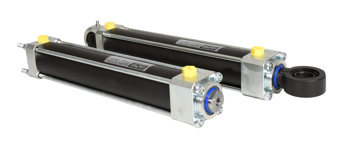
Lalmek KC hydraulic cylinders are of the tie-rod type where the cylinder is screwed together with four tie-rods. This design is ideal for demanding applications where vibration and pressure peaks are common as there are no welded joints.
The hydraulic cylinders have compact installation dimensions and can be supplied with a number of different fastening options at both the piston rod end and the cylinder short end, such as spherical ends, internal or external threads or for mounting with bolted joints.
Lalmek KC can be equipped with integrated linear sensors that state the position of the piston rod with great accuracy.
The hydraulic cylinders are available in cylinder diameters up to 250 mm and press force up to 100 tons.
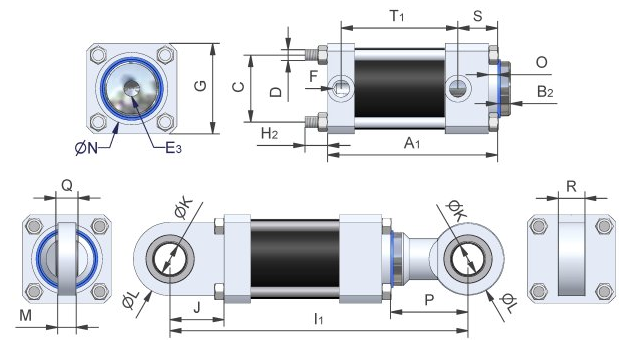
| Max. pressure (bar) | (Max. pressure on request) | Pressure force at 200 bar (tonne) | Tractive force at 200 bar (tonne) | Pressure area (cm²) | Tractive area (cm²) | Cylinder diameter (int.) | Piston rod diameter | A +- 2mm | B (2) | C | D | E (3) | F | G | H (2) | I +- 2mm (1) | J | K | L | M (bearing housing width) | N (tolerance f8) | O | P | Q (ball width) | R (bearing housing width) | S | T (1) | |
|---|---|---|---|---|---|---|---|---|---|---|---|---|---|---|---|---|---|---|---|---|---|---|---|---|---|---|---|---|
| 25/16 | 300 | 1 | 0,6 | 4,9 | 2,9 | 25 | 16 | 90 | 10 | 28 | M6 | M10 | G1/4" | 40 | >15 | 138,5 | 20 | 12 | 40 | 12 | 27 | 8 | 27,5 | 10 | 12 | 27,5 | 51 | |
| 32/20 | 260 | 300 | 16 | 1 | 8 | 4,9 | 32 | 20 | 96 | 10 | 32,6 | M6 | M10 | G1/4" | 45 | >15 | 146,5 | 18 | 15 | 47 | 18 | 34 | 10 | 32,5 | 12 | 18 | 26,5 | 58 |
| 40/24 | 290 | 300 | 2,5 | 1,6 | 12,6 | 8 | 40 | 24 | 105 | 10 | 41 | M8 | M12 | G1/4" | 66 | >20 | 167,5 | 27,5 | 20 | 55 | 20 | 42 | 10 | 35 | 16 | 20 | 25,5 | 69 |
| 40/30 | 290 | 300 | 2,5 | 1,1 | 12,6 | 5,5 | 40 | 30 | 105 | 10 | 41 | M8 | M12 | G1/4" | 55 | >20 | 167,5 | 27,5 | 20 | 55 | 20 | 42 | 8 | 35 | 16 | 20 | 25,5 | 69 |
| 50/30 | 200 | 260 | 3,9 | 2,5 | 19,6 | 12,6 | 50 | 30 | 123 | 10 | 48 | M8 | M12 | G3/8" | 62 | >20 | 190 | 31 | 25 | 62 | 25 | 52 | 10 | 40 | 20 | 25 | 37 | 74 |
| 60/33 | 200 | 280 | 5,7 | 3,9 | 28,3 | 19,6 | 60 | 33,2 | 131 | 10 | 58 | M10 | M16 | G3/8" | 80 | >25 | 207 | 35 | 30 | 80 | 30 | 62 | 10 | 45 | 22 | 30 | 42 | 77 |
| 60/40 | 200 | 280 | 5,7 | 3,1 | 28,3 | 15,7 | 60 | 40 | 131 | 10 | 58 | M10 | M16 | G3/8" | 80 | >25 | 207 | 35 | 30 | 80 | 30 | 62 | 10 | 45 | 22 | 30 | 42 | 77 |
| 70/36 | 230 | 280 | 7,7 | 5,7 | 38,5 | 28,3 | 70 | 36 | 131 | 10 | 66 | M12 | M20 | G1/2" | 88 | >25 | 263 | 61 | 35 | 83 | 21 | 70 | 10 | 71 | 25 | 30 | 33 | 82,5 |
| 80/39 | 200 | 240 | 10,1 | 7,7 | 50,3 | 38,5 | 80 | 38,7 | 134,3 | 10 | 74 | M12 | M20 | G1/2" | 100 | >25 | 266,3 | 61 | 35 | 83 | 21 | 80 | 10 | 71 | 25 | 30 | 34 | 85,3 |
| 80/60 | 200 | 240 | 10,1 | 4,4 | 50,3 | 22 | 80 | 60 | 144,3 | 20 | 74 | M12 | M20 | G1/2" | 100 | >25 | 286,3 | 61 | 35 | 83 | 21 | 80 | 10 | 81 | 25 | 30 | 44 | 85,3 |
| 100/60 | 200 | 15,7 | 10,1 | 85,5 | 50,3 | 100 | 60 | 178 | 20 | 90 | M16 | M24 | G1/2" | 120 | >30 | 374 | 88 | 50 | 123 | 30 | 92 | 15 | 108 | 35 | 40 | 60 | 101 | |
| 100/75 | 200 | 15,7 | 6,9 | 78,5 | 34,3 | 100 | 75 | 178 | 20 | 90 | M16 | M24 | G1/2" | 120 | >30 | 374 | 88 | 50 | 123 | 30 | 96 | 15 | 108 | 35 | 40 | 60 | 101 | |
| 125/75 | 210 | 240 | 24,5 | 15,7 | 122,7 | 78,5 | 125 | 75 | 178 | 20 | 114 | M20 | M24 | G1/2" | 150 | >40 | 374 | 88 | 50 | 123 | 30 | 105 | 15 | 108 | 35 | 40 | 60 | 101 |
| 160/100 | 250 | 40,2 | 24,5 | 201,1 | 122,5 | 160 | 100 | 210 | 20 | 150 | M30 | M42 | G3/4" | 20 | >50 | 492 | 141 | 80 | 180 | 47 | 150 | 15 | 161 | 55 | 60 | 54,3 | 115,8 | |
| 200/120 | 290 | 290 | 62,8 | 40,2 | 314,2 | 201,1 | 20 | 120 | 293 | 20 | 190 | M36 | M80x3 | G1 1/4" | 250 | >50 | 170 | 100 | 250 | 163 | 20 | 70 | 70 | 77 | 188,5 | |||
| 250/150 | 300 | 98,2 | 62,8 | 490,9 | 314,2 | 250 | 150 | 265,5 | 40 | 244 | M45 | M100x3 | G1 1/2" | 320 | >75 | 210 | 120 | 360 | 200 | 20 | 85 | 90 | 74,5 | 160 |
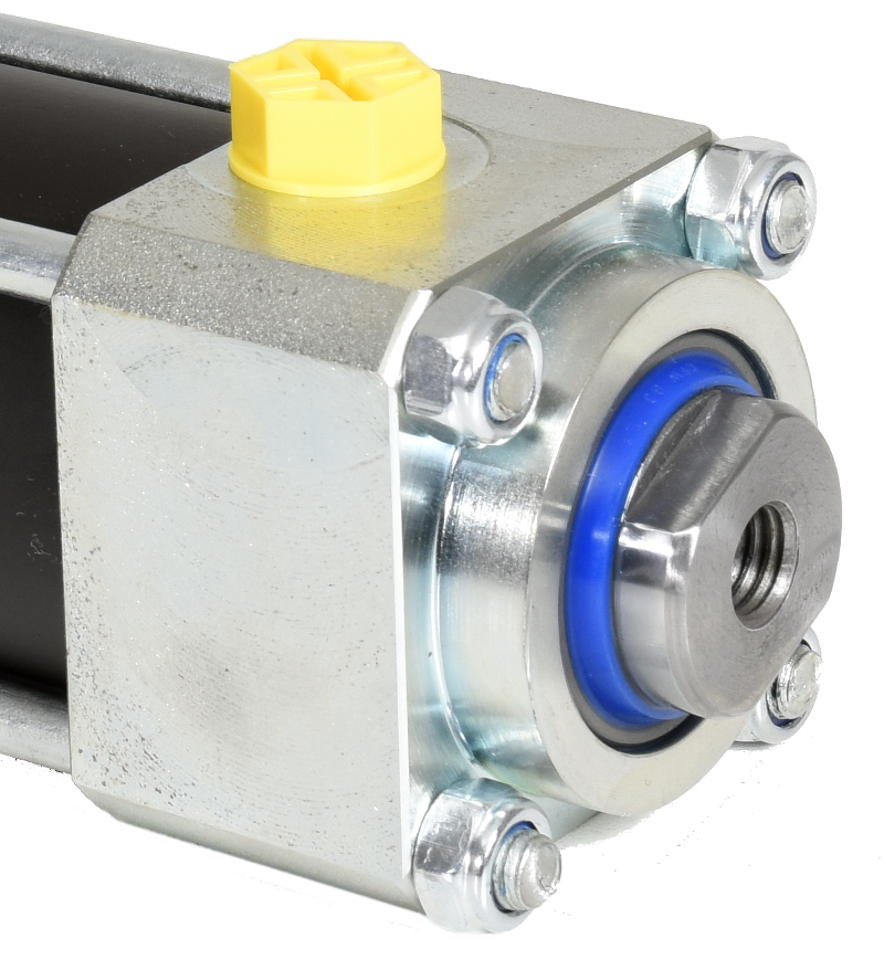
Hydraulic cylinder KC with internal threads in the piston rod
The piston rod is available with an internal thread and spanner flats as required.
The tie rods can be combined with a guide collar on the front short-end to fasten the hydraulic cylinder in e.g. a tool.
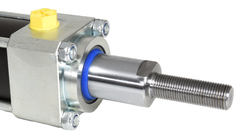
Hydraulic cylinder KC with external thread on the piston rod.
The piston rod is available with an external screw thread and spanner flats as required.
The tie rods can be combined with a guide collar on the front short-end to fasten the hydraulic cylinder in e.g. a tool.
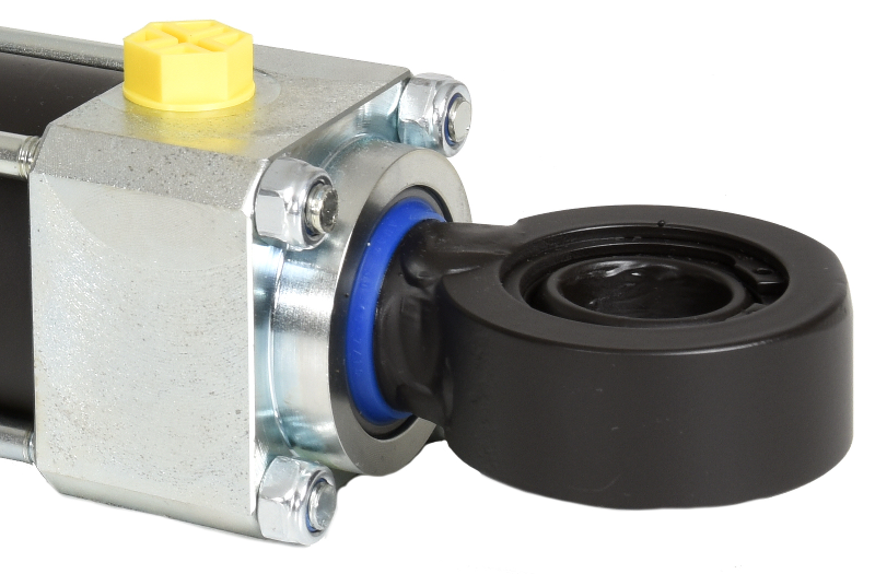
Hydraulic cylinder KC with rod ends (uniballs) on the piston rod.
Available with welded rod-ends or a rod-end that is screwed onto the piston rod, which gives adjustment possibilities.
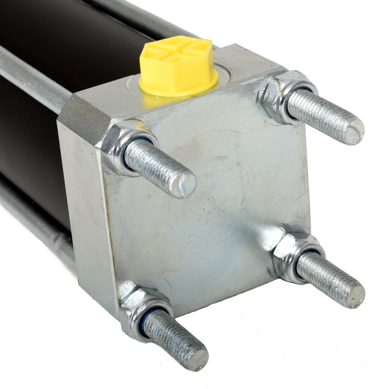
Hydraulic cylinder KC with flat, rear short-end.
Fastening by means of the tie-rods.
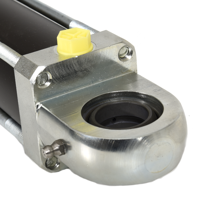
Hydraulic cylinder KC with horizontal rod-end at the rear, short-end
Fastening occurs using the horizontal rod-end in relation to the connection.
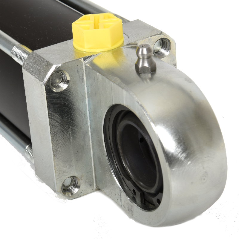
Hydraulic cylinder KC with vertical rod-end at the rear, short-end
Fastening occurs using the vertical rod-end in relation to the connection.